- 您现在的位置:买卖IC网 > Sheet目录2007 > MAX11101EUB+ (Maxim Integrated Products)IC ADC 14BIT SRL 200KSPS 10UMAX
Maxim Integrated Products 15
MAX11101
14-Bit, +5V, 200ksps ADC with 10A Shutdown
QSPI Interface
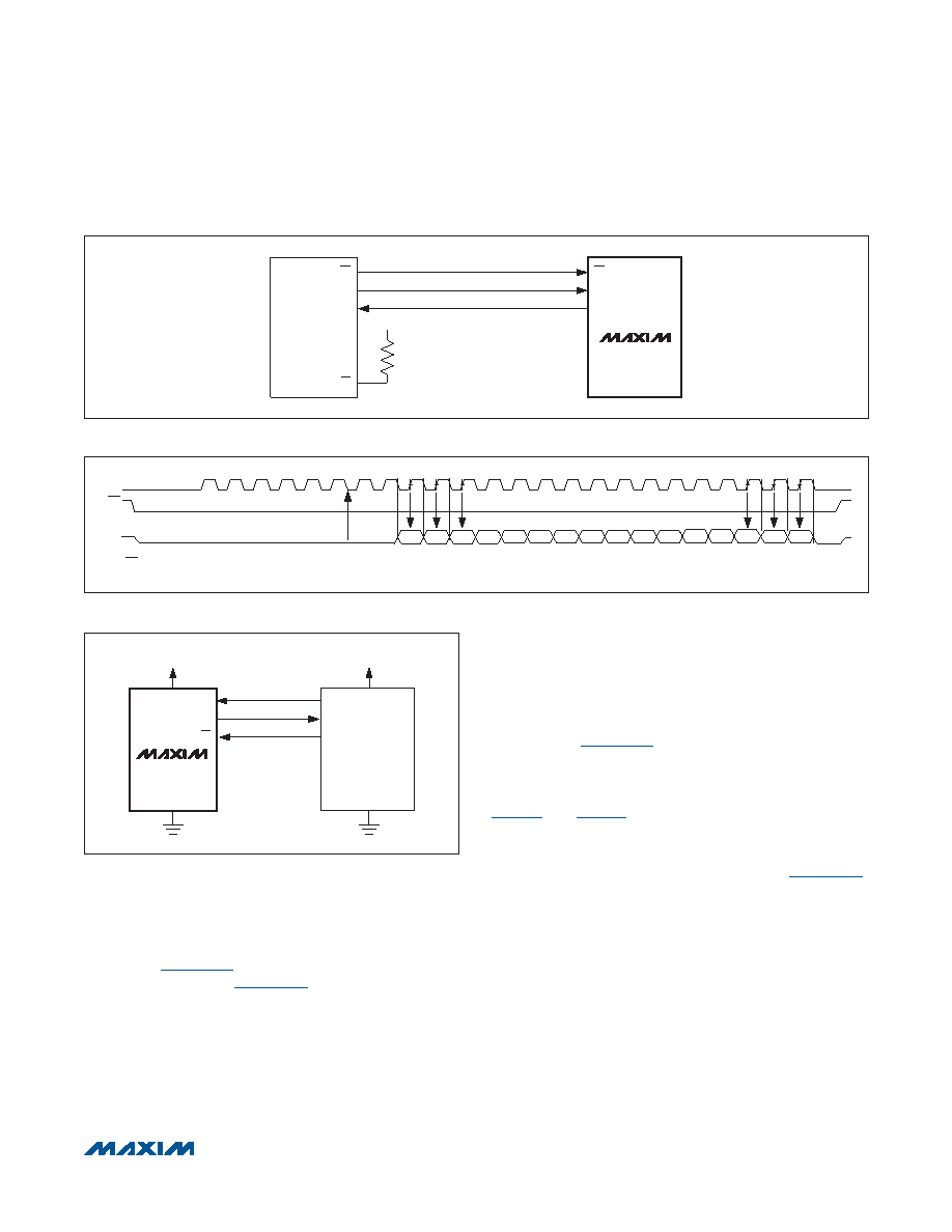
Using the high-speed QSPI interface with CPOL = 0 and
CPHA = 0, the MAX11101 supports a maximum fSCLK
of 4.8MHz. Figure 11a shows the MAX11101 connected
to a QSPI master and Figure 11b shows the associated
interface timing.
PIC16 with SSP Module and PIC17 Interface
The MAX11101 is compatible with a PIC16/PIC17 micro-
controller (FC) using the synchronous serial-port (SSP)
module.
To establish SPI communication, connect the controller
as shown in Figure 12a. Configure the PIC16/PIC17 as
system master, by initializing its synchronous serial-port
control register (SSPCON) and synchronous serial-port
status register (SSPSTAT) to the bit patterns shown in
In SPI mode, the PIC16/PIC17 FC allows 8 bits of data
to be synchronously transmitted and received simulta-
neously. Three consecutive 8-bit readings (Figure 12b)
are necessary to obtain the entire 14-bit result from the
ADC. DOUT data transitions on the serial clock’s falling
edge and is clocked into the FC on SCLK’s rising edge.
The first 8-bit data stream contains all zeros. The second
8-bit data stream contains the MSB through D6. The third
8-bit data stream contains bits D5 through D0 followed
by S1 and S0.
Figure 11a. QSPI Connections
Figure 11b. QSPI Interface Timing Sequence (CPOL = CPHA = 0)
Figure 12a. SPI Interface Connection for a PIC16/PIC17
CS
QSPI
SCLK
DOUT
CS
SCK
MISO
VDD
SS
MAX11101
DOUT*
CS
SCLK
*WHEN CS IS HIGH, DOUT = HIGH-Z
MSB
20
16
D13 D12 D11 D10
D9
D8
D7
HIGH-Z
S1
S0
24
12
14
8
6
D6
D3
D2
D1
LSB
D5
D4
END OF
ACQUISITION
D0
SCK
SDI
GND
PIC16/17
I/O
SCLK
DOUT
CS
VDD
MAX11101
发布紧急采购,3分钟左右您将得到回复。
相关PDF资料
MAX11102AUB+
IC ADC 12BIT SPI/SRL 10UMAX-EP
MAX1111CPE+
IC ADC 8BIT LP 16-DIP
MAX1113CPE+
IC ADC 8BIT LP 16-DIP
MAX1116EKA+T
IC ADC 8BIT SERIAL SOT23-8
MAX11201BEUB+T
IC ADC 24BIT SRL 13.75SPS 10UMAX
MAX11202BEUB+T
IC ADC 24BIT SRL 13.75SPS 10UMAX
MAX11210EEE+T
ADC 24BIT 4WIRE SPI 16-QSOP
MAX11212BEUB+T
IC ADC 18BIT SRL 13.75SPS 10UMAX
相关代理商/技术参数
MAX11101EUB+T
功能描述:模数转换器 - ADC 14-Bit 5V 200ksps w/10uA Shutdown RoHS:否 制造商:Texas Instruments 通道数量:2 结构:Sigma-Delta 转换速率:125 SPs to 8 KSPs 分辨率:24 bit 输入类型:Differential 信噪比:107 dB 接口类型:SPI 工作电源电压:1.7 V to 3.6 V, 2.7 V to 5.25 V 最大工作温度:+ 85 C 安装风格:SMD/SMT 封装 / 箱体:VQFN-32
MAX11101EWC
制造商:MAXIM 制造商全称:Maxim Integrated Products 功能描述:14-Bit, +5V, 200ksps ADC with 10μA Shutdown
MAX11101EWC+
制造商:MAXIM 制造商全称:Maxim Integrated Products 功能描述:14-Bit, 5V, 200ksps ADC with 10??A Shutdown
MAX11101EWC+T
功能描述:模数转换器 - ADC 14-Bit 5V 200ksps w/10uA Shutdown RoHS:否 制造商:Texas Instruments 通道数量:2 结构:Sigma-Delta 转换速率:125 SPs to 8 KSPs 分辨率:24 bit 输入类型:Differential 信噪比:107 dB 接口类型:SPI 工作电源电压:1.7 V to 3.6 V, 2.7 V to 5.25 V 最大工作温度:+ 85 C 安装风格:SMD/SMT 封装 / 箱体:VQFN-32
MAX11102
制造商:MAXIM 制造商全称:Maxim Integrated Products 功能描述:2Msps/3Msps, Low-Power, Serial 12-/10-/8-Bit ADCs
MAX11102_11
制造商:MAXIM 制造商全称:Maxim Integrated Products 功能描述:2Msps/3Msps, Low-Power, Serial 12-/10-/8-Bit ADCs 2.2V to 3.6V Supply Voltage
MAX11102_1108
制造商:MAXIM 制造商全称:Maxim Integrated Products 功能描述:2Msps/3Msps, Low-Power, Serial 12-/10-/8-Bit ADCs
MAX11102ATB
制造商:MAXIM 制造商全称:Maxim Integrated Products 功能描述:2Msps/3Msps, Low-Power, Serial 12-/10-/8-Bit ADCs 2.2V to 3.6V Supply Voltage